Thermoelectric Cooler
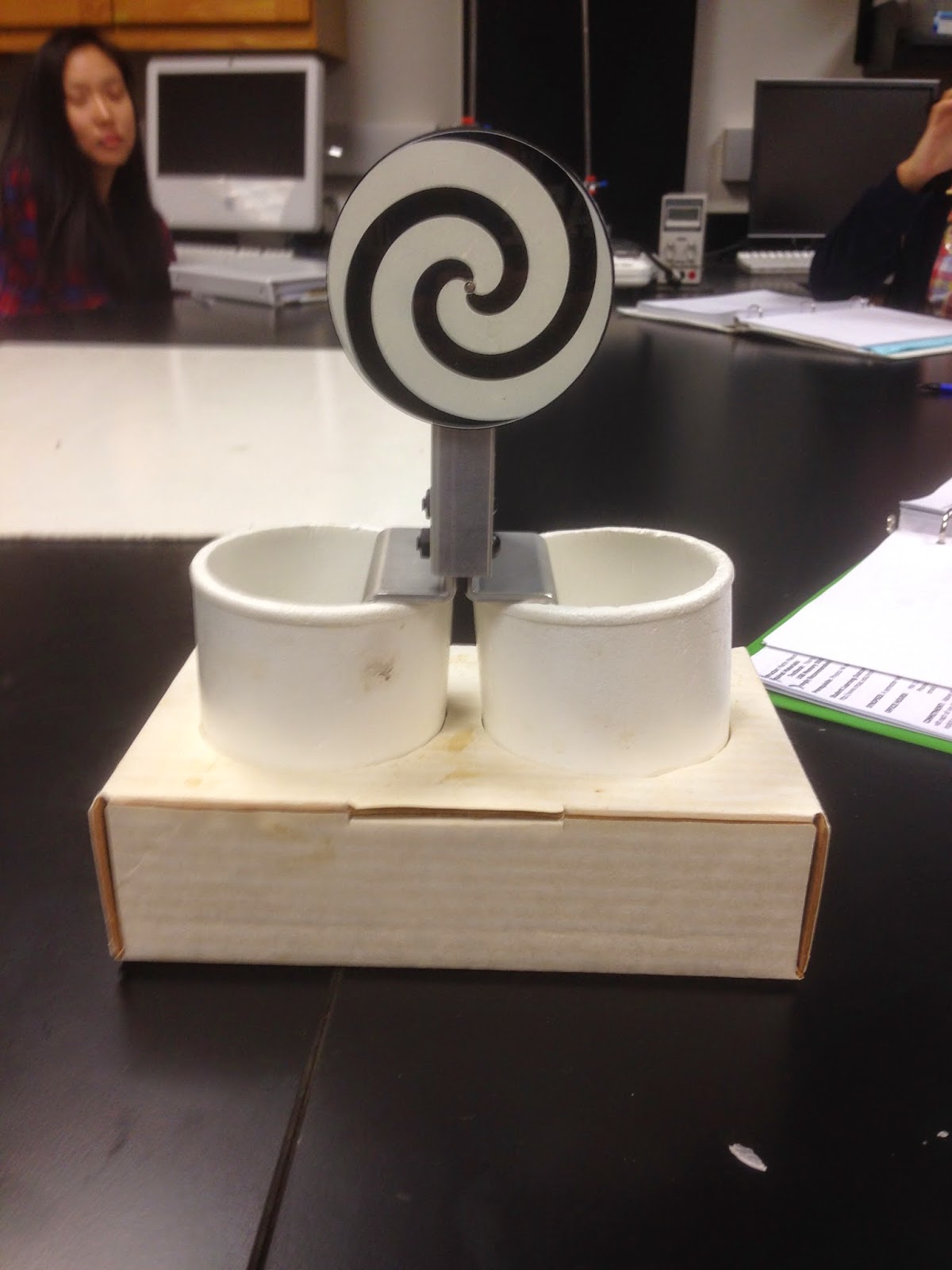 |
| hypnotic circle |

Hot water was poured into one cup and cold water is poured
into another cup. The thermoelectric
cooler has two metal sides that stick out of it like a tuning fork and one side
is placed into the hot water and the other is placed into the cold water. The temperature of the hot and cold water
stay relatively constant so it can be said that the change in temperature is
0. Because the temperature stays
relatively constant, then it can be seen that the change in heat transfer will
equal work. So as the heat begins to
transfer from the hot water to the cold water, it generates work and the
hypnotic circle begins to spin. If you
were to turn the thermoelectric cooler around and now have the metal side that
was in the hot water now be in the cold water and the metal side that was in
the cold water now be in the hot, then the hypnotic circle should begin to spin
the opposite direction meaning that this is an example of a reversible heat
engine.
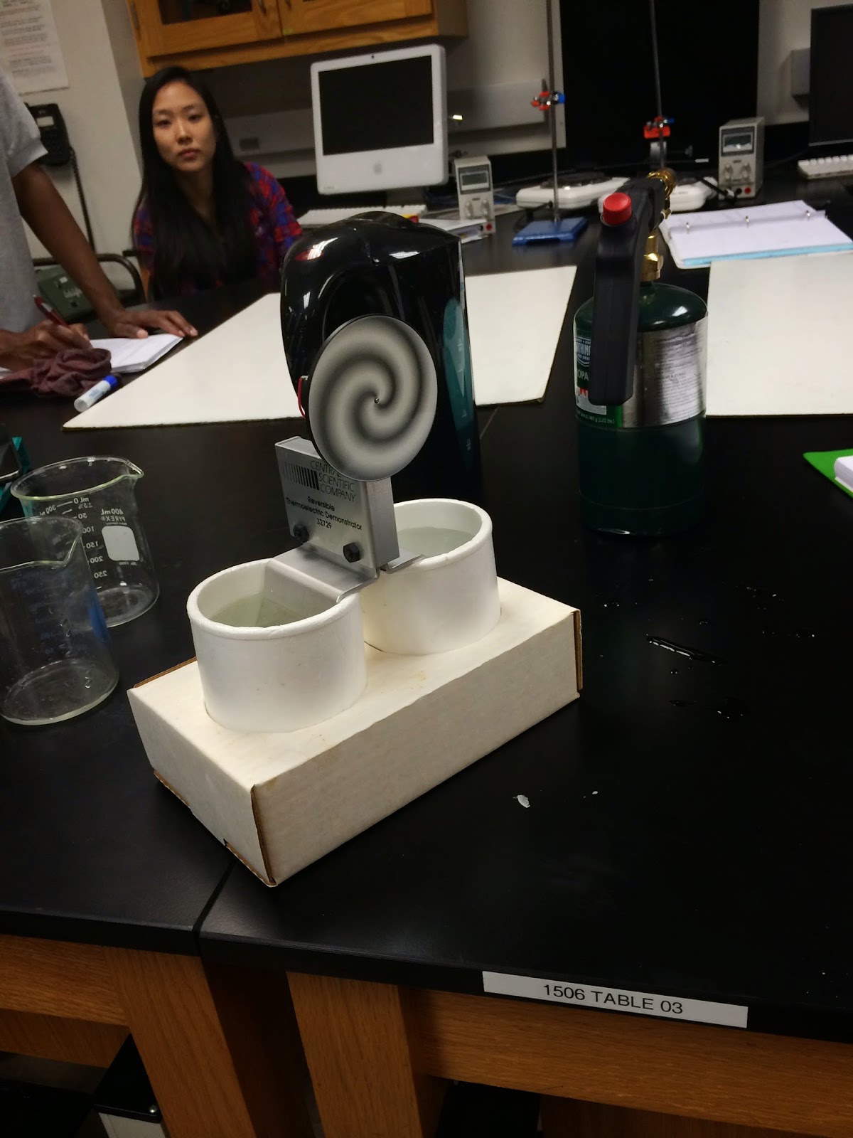 |
| Moving Hypnotic Circle |
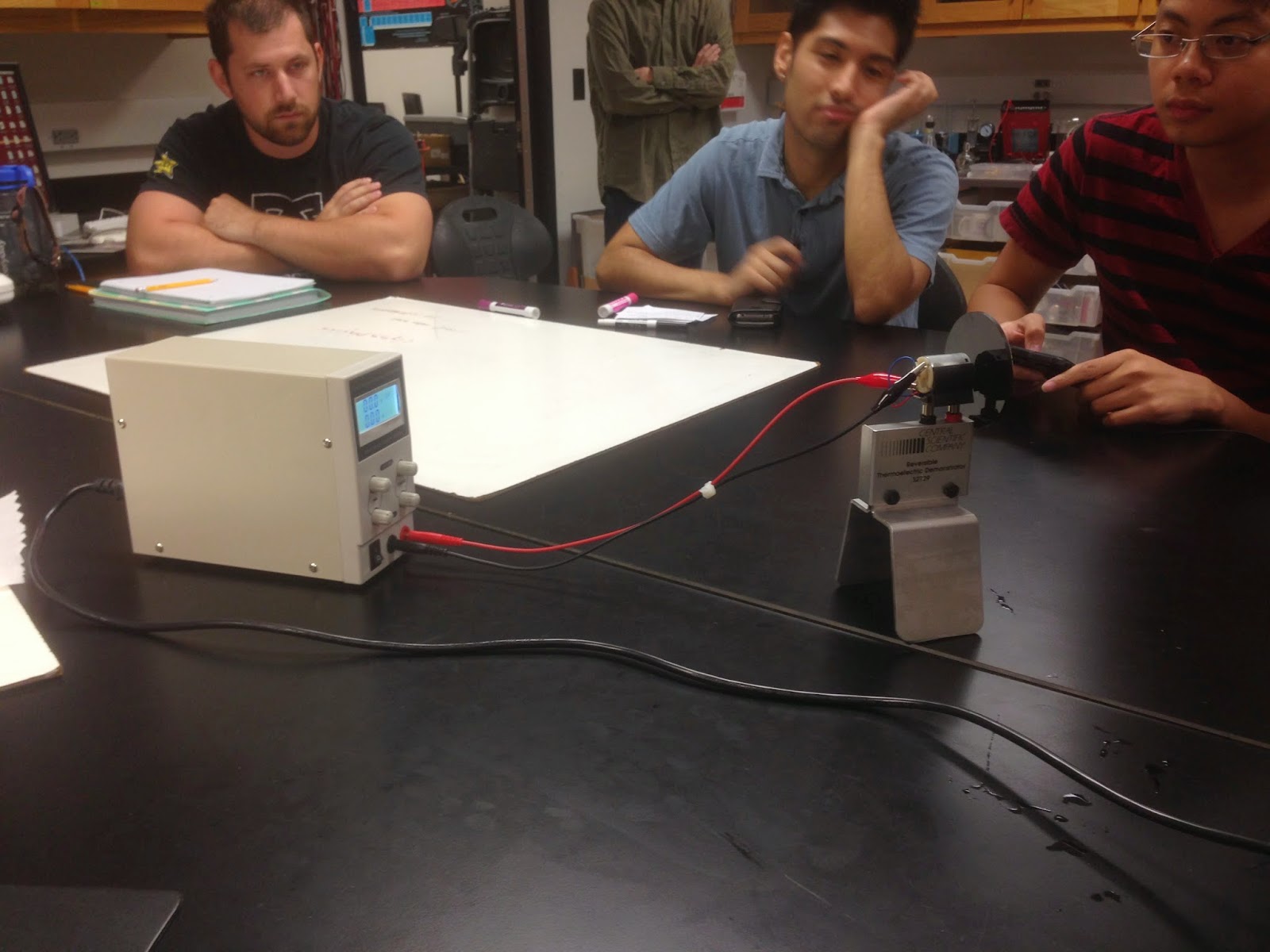 |
| Hypnotic Circle Attached to Power Source |

Next we attached a power source directly to the hypnotic circle
without it being placed in any water and it began to spin. After having this system spin for a minute, it
could be observed that there was a heat transfer between the two metal feet at
the bottom of the thermoelectric cooler.
This is because the temperature never really changes to the work done on
the object is equal to the change in heat transfer. So the work that was being generated allowed
for heat transfer between the two metal poles.
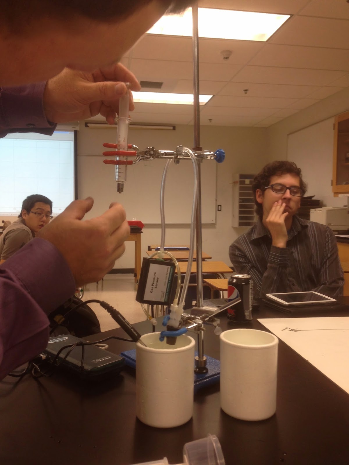 |
| Incredible Mass Lifter Set-up |
Incredible Mass Lifter

We began this experiment with two different cups of water,
one hot one cold, a flask with a plunger on the top and a frictionless piston
that is attached to the flask/plunger and also to a pressure sensor so the
pressures can be recorded. We found the
initial volume of the system and recorded that and then placed the 84 gram
weight on top of the piston while the flask was placed into the cold water. As the weight is placed on the piston, the
volume goes down lowering the mass and the pressure goes up which can be seen
as an isothermal process because the temperature of the cold water stayed the
same. Next, the flask is moved from the
cold water to the hot water, so the temperature goes up and the volume goes up,
raising the mass, which makes this an isobaric process because the pressure
remained the same. After the mass was
raised, it was removed which increased the volume and decreased the pressure of
the system which made this process isothermal because the flask stayed in the
hot water. After the piston moved up
from removing the mass, the flask was then placed back into the bath of cold
water which decreased the temperature and volume of the system, returning the
piston to its original position, while the pressure remained the same which
made it an isobaric process.

After the
whole four step process was completed, a square type shape was shown on a
position vs volume graph that was made with logger pro. It can be seen that the area under a pressure
vs volume graph is the sum of the work done, so before retrieving the actual
work done from logger pro, we first calculated it with triangles and squares
drawn within the curve. I calculaculated
the area under the curve to be 25.599 cc/kPa which, after rounding up, is
identical to the logger pro value which was 26 cc/kPa.
Ideal Heat Engine Gas Cycle
 |
| Explaining intake/compression strokes |
This Heat Engine is a four stroke process. It goes through an intake/exhaust stroke,
compression stroke, an ignition stroke, and an expansion stroke. First, in the intake stroke, the valve opens
as the piston goes down. When the piston
is in the process of going down, it is creating a vacuum so that fresh air and
fuel can be pulled in by the open valve.
In this step, the volume and number of moles are changing making this an
isobaric process. Next, in the
compression stroke, the valves are closed so as the piston moves up the volume
and pressure are changing rapidly making an adiabatic compression of gas fuel
mixture in the cylinder. After, the
ignition stroke takes place and the air fuel mixture rapidly ignites at top of
the compression stroke while the volume is essentially constant making this
part of the process an isochoric one.
From the extreme increase in pressure, the piston gets pushed down and
the expansion stroke takes place. This
is another adiabatic process because the volume is being increased which in
turn decreases the pressure, this the part of the cycle that does positive
work.

.JPG)
No comments:
Post a Comment