 |
| Capacitors in Parallel |
Capacitors in Series and Parallel
 |
| capacitors in series |

 Two capacitors of the same capacitance ( .1E-06 F) were
connected first in parallel and then in series.
When the capacitors were hooked up in parallel with alligator clips, a
multimeter was used to measure the capacitance which was 1.945E-06 F while the
capacitance hooked up in series was measured with the multimemter to be only
.482E-06 F. The relationships can be
seen between capacitors connected in series and in parallel (see whiteboard)
Two capacitors of the same capacitance ( .1E-06 F) were
connected first in parallel and then in series.
When the capacitors were hooked up in parallel with alligator clips, a
multimeter was used to measure the capacitance which was 1.945E-06 F while the
capacitance hooked up in series was measured with the multimemter to be only
.482E-06 F. The relationships can be
seen between capacitors connected in series and in parallel (see whiteboard)
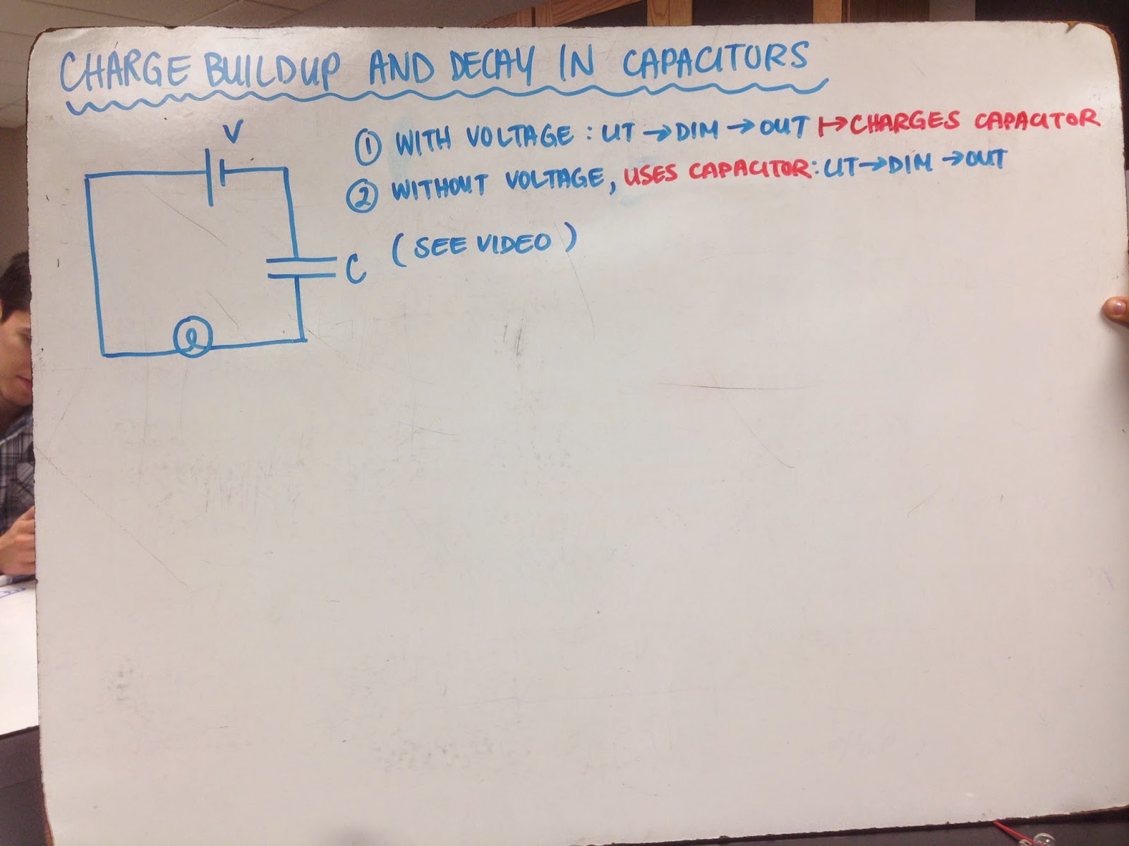
Charge Buildup and Decay in Capacitors
 A capacitor, a source of voltage, and a light bulb were all
connected in series. First the light bulb
was lit and then as the capacitor was charged the light bulb dimmer and
dimmer until it turned off. Then the
connections were taken out of the voltage source and touched to one another to
create another series circuit but without the voltage source. The light bulb lit up and the went dimmer and
dimmer until it went out. The light bulb
was able to light up without the voltage source because the capacitor was
charged with energy.
A capacitor, a source of voltage, and a light bulb were all
connected in series. First the light bulb
was lit and then as the capacitor was charged the light bulb dimmer and
dimmer until it turned off. Then the
connections were taken out of the voltage source and touched to one another to
create another series circuit but without the voltage source. The light bulb lit up and the went dimmer and
dimmer until it went out. The light bulb
was able to light up without the voltage source because the capacitor was
charged with energy.
A Capacitance Puzzle
 Two separate capacitors each of charge .47 F were each
connected to a voltage source one with voltage 3.0 V and the other with voltage
4.5V. Then the capacitors were unhooked
from their batteries and hooked to eachother without being discharged. We predicted that the voltage across the two
would end up being an average of the two voltages. A system of equations were used to solve this
problem and we know that when there is no discharge that the final sum of the
charges on the two capacitors is actually the average sum (like an equilibrium
point). We solved for the voltage in the
final set up where the capacitors were connected to one another and solved the
value to be 3.74. We then measure the
actual voltage between the two capacitors with a multimeter which was found to
be 3.94 and found that there was a 5.8 % error between the two numbers probably
due to the fact that the capacitors we used when measuring the voltage with the
multimeter were .56 F not .47 F.
Two separate capacitors each of charge .47 F were each
connected to a voltage source one with voltage 3.0 V and the other with voltage
4.5V. Then the capacitors were unhooked
from their batteries and hooked to eachother without being discharged. We predicted that the voltage across the two
would end up being an average of the two voltages. A system of equations were used to solve this
problem and we know that when there is no discharge that the final sum of the
charges on the two capacitors is actually the average sum (like an equilibrium
point). We solved for the voltage in the
final set up where the capacitors were connected to one another and solved the
value to be 3.74. We then measure the
actual voltage between the two capacitors with a multimeter which was found to
be 3.94 and found that there was a 5.8 % error between the two numbers probably
due to the fact that the capacitors we used when measuring the voltage with the
multimeter were .56 F not .47 F.
Quantitative Measurements on an RC System
 |
| set up |
First we measured the voltage across a charged capacitor as
a function of time when a carbon resistor has been placed ina circuit with
it. With the voltage source connected,
the graph rises and the levels off and then when the voltage source is
disconnected the voltage begins to drop.
(These graphs can be seen on whiteboard) We fit an equation for these
graphs and found that they are slightly different for when the voltage source
is connected (charging) and when the voltage source is disconnected (discharging). For the charging capacitor, the voltage
equation is A(1-e^(-cb)) and for the discharging capacitor the voltage equation
is Ae^(-cb). After doing unit analysis,
it can be seen that A is the max voltage, and cb is equal to t/RC. Using the data from the graphs, the
experimental value for t/RC was -.3620 for the charging capacitor and .3571 for
the discharging capacitor. We calculated
the actual value for t/RC with the equipment we used and found it to be
.4. We found that there was a 9.97 and
11.3 % error respectively.


 |
| graphs |
No comments:
Post a Comment